
Welcome to the 4th part of the NSX Advanced Load Balancer Integration with VMware Cloud Director series. The first post in this series covered Service Engine design topologies, while the second covered the processes for enabling “Load Balancing as a Service” in VCD. The deployment of the Dedicated Service Engine design was demonstrated in the third post.
This post will talk about the implementation of the Shared Service Engines design.
If you haven’t read the previous posts in this series, I recommend you do so using the links provided below.
1: NSX ALB Integration with VCD – Supported Designs
3: Implementing Dedicated Service Engine Groups Design
In Shared Service Engine Group design, tenant’s Edge Gateways can leverage a common Service Engine Group for the load balancer and virtual services placement. Since VCD tenants can have overlapping org networks implemented in their respective org’s, data traffic segregation is achieved by implementing VRF’s in NSX ALB.
In this design, when load balancing is enabled for an edge gateway, the edge gateway plumbs a NIC (for carrying data traffic) on the Service Engine VM. The Data NIC is internally mapped to a dedicated vrf context in the Service Engine. A Service Engine can have up to 10 data interfaces, so 10 edge gateways can be connected to a Service Engine. When a Service Engine runs out of data interfaces, NSX ALB can deploy a new Service Engine (In fully orchestrated mode) in the SEG for the placement of the load balancer objects.
The below diagram shows the typical architectural design of a Shared SEG.
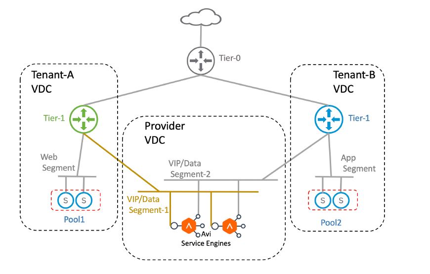
Graphic Thanks to VMware
It’s time to dive into the lab and walk through the steps of implementing a Shared SEG design.
Step 1: Create SEG
Login to the NSX ALB Controller and navigate to the Infrastructure > Service Engine Group page. Select the NSX-T cloud that you have created and click on the create button.
Provide a name for the SEG and configure HA and Placement settings etc. The VS Placement and HA mode dictate how Virtual Services are placed on the Service Engines.
- In Compact mode, Service Engine hosts multiple Virtual Services until the “Virtual Services per SE” limit is reached.
- In Distributed mode, every time a Virtual Service is created, a new Service Engine is deployed until the “Max Number of SE’s/SEG” is reached. When the limit is reached, newly created virtual services are deployed on existing SEs.
In Active-Active HA mode, Virtual Services are placed on more than one SE. In N+M mode, Virtual Services are placed on a single Service Engine. When a Service Engine fails, virtual services are failed over to a new or existing Service Engine.
Step 2: Import SEG in VCD
Login to VCD as System Admin user and navigate to Resources > Infrastructure Resources > NSX ALB > Service Engine Groups and click on the Add button.

Select the Reservation Model as Shared and the SEG created in step 1.

The SEG can now be assigned to multiple tenants.
Step 3: Associate SEG with Tenant’s Edge Gateway
To associate the tenant’s edge gateway with the SEG, navigate to the Resources > Cloud Resources > Edge Gateways and click on the tenant’s gateway.
Under Load Balancer, edit the General Settings to enable Load Balancing on the tenant’s org.
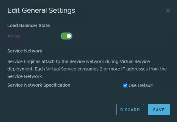
After load balancing is enabled for the tenant, select the Service Engine Groups page and click on the Add button.
Select the Shared SEG that you imported earlier and configure the VS Reservations for the tenant.

The tenant can configure load balancer constructs on the edge gateway. In the next post of this series, I will demonstrate the deployment of a load balancer. Stay tuned!!!
I hope you enjoyed reading this post. Feel free to share this on social media if it is worth sharing.