
Table of Contents
Overview
NSX Advanced Load Balancer provides multi-cloud load balancing, web application firewall, application analytics, and container ingress services from the data center to the cloud. It is an Intent-based software load balancer that provides scalable application delivery across any infrastructure. NSX ALB provides 100% software load balancing to ensure a fast, scalable and secure application experience. It delivers elasticity and intelligence across any environment.
With the release of VCD 10.2, NSX Advanced Load Balancer integration is available for use by the tenants. Service Provider configured NSX ALB and exposes load balancing functionality to the tenants so that tenants can deploy load balancers in a self-service fashion.
The latest release of VCD (10.3.1) supports NSX ALB versions up to 21.1.2. Please check the VMware product interop matrix before planning your deployment.

In this blog post, I will be talking about the NSX ALB design patterns for VCD and the ALB integration steps with VCD.
Please note that the scope of this document is limited to the NSX ALB configuration part and does not cover any deployment procedures for the underlying SDDC components, VCD, and NSX ALB.
NSX ALB Design Patterns in VCD
Service Engine is the brain of the NSX ALB. It handles all data plane operations by receiving and executing instructions from the controller. The SEs perform load balancing and all client- and server-facing network interactions.
NSX ALB is a multi-tenant solution and depending upon the use case, the following design patterns are available in VCD:
- Shared Service Engine Group (SEG) Design
- Dedicated Service Engine Group (SEG) Design
Dedicated Service Engines per VCD tenant
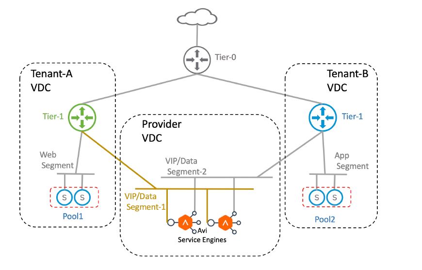
In this design, each VCD tenant has access to a dedicated Service Engine Group (SEG) where Service Engines can be deployed to host Virtual Services, VIP and Server Pool, etc. There is a 1:1 mapping between the Edge Gateway (OrgVDC Gateway) and the SEG.
In this design, each Service Engine is connected to one VIP/Data network. This VIP network is a logical segment on the tenant’s Tier-1 gateway.
The general network layout for a Dedicated Service Engine deployment in VCD looks as shown below.

Graphic Thanks to VMware
This design is appropriate for tenants who require guaranteed Service Engine performance as well as traffic isolation for their virtual services.
The following are the key considerations for putting this design into action:
- Service Provider provisions the Tier-1 gateway for the tenant directly from NSX-T.
- Service Engine management network is manually created by the provider and attached to the Tier-1 gateway dedicated for NSX ALB.
- DHCP is required on the management logical segment so that Service Engines can obtain their management interface (eth0) IP address automatically.
- VIP network is automatically created when virtual service is hosted on the Serice Engine. This VIP network gets attached to the Tier-1 gateway of the tenant.
- The service engines are deployed in one-arm mode, i.e. the same interface is used for client and backend server traffic. The SE routes to backend servers through the tier-1 router.
- The VIPs can be allocated from the same subnet as that of the VIP/Data interface of the Service engine.
- A range of static IP addresses must be reserved in the subnet assigned to the VIP/Data segment, to be used as VIPs.
Shared Service Engines for VCD tenants
In this design, VCD tenants leverage Service Engines from a shared Service Engine Group to host their Virtual Services, VIPs, etc. The data plane is shared between the tenant’s applications and the traffic isolation is achieved through VRF context.
The general network layout for a Shared Service Engine deployment looks as shown below.
Graphic Thanks to VMware
Since Service Engines are shared between the tenants:
- The VIP network of each tenant gets plumbed to the Service Engine.
- Each VIP network maps to a dedicated VRF context in the Service Engine.
- Since there are only 9 data interfaces on the Service Engine, each SE can be shared between 9 tenants. However, you can deploy additional Service Engines in the shared SEG to be shared with tenants.
- VRF is configured per tenant in the NSX ALB controller by the Service provider. The VIP network of each tenant is mapped to the respective VRF.
- Tenants can have overlapping subnets as the routing table is maintained per VRF in the SE.
Management Plane Connectivity
In this section, I will discuss Service Engine connectivity with NSX ALB controllers as well as the placement of the controller nodes.
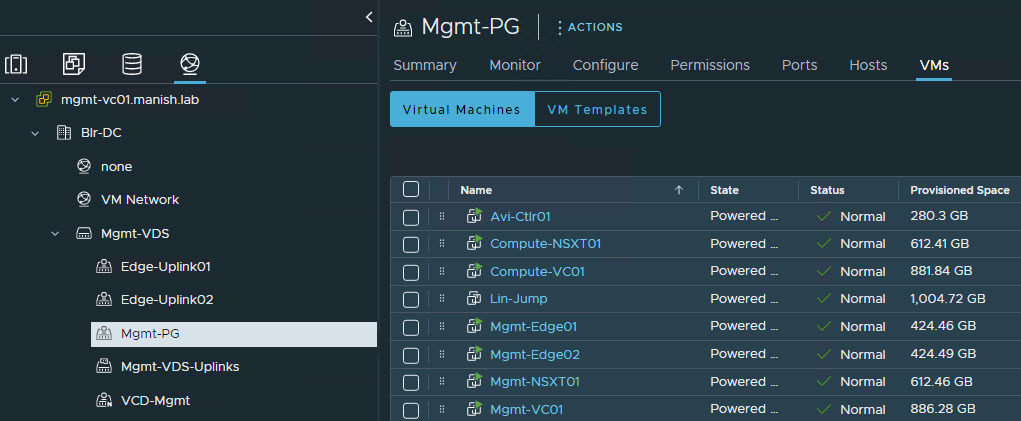
NSX ALB controller nodes are placed in the management vCenter and connected to the port group where vCenter and NSX-T nodes of the compute cluster are connected.
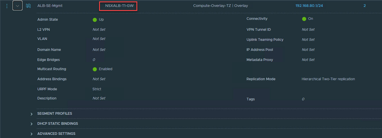
NSX ALB Service Engines are deployed in the Compute vCenter. A dedicated Tier-1 gateway (let’s call it management tier-1 gateway) is created in compute NSX-T and a segment for SE management interface (eth0) is attached to this Tier-1 gateway.
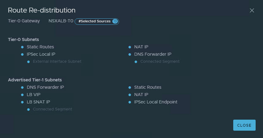
The management tier-1 gateway is configured to redistribute connected routes to the management tier-0 gateway.

The management tier-0 gw is configured to advertise the SE management subnet to ToR using BGP.
NSX ALB controller in the management cluster should be able to talk to the SE management interface advertised subnet via its ToR.
Please note that management Tier-0 & Tier-1 gw are used only for NSX ALB connectivity. Your regular applications network doesn’t connect to these gateways. For that, you need a separate Tier-0 & Tier-1 gw created in the compute NSX-T.
And that’s it for this post. In the next post of this series, I will cover the steps of implementing Dedicated Service Engine Group design. Stay tuned!!!
I hope you enjoyed reading this post. Feel free to share this on social media if it is worth sharing.