
Load balancers are an integral part of any data center, and most of the enterprise applications are clustered for high availability and load distribution. The choice of the load balancer becomes very critical when applications are distributed across data centers/clouds.
This blog series is focused on demonstrating how we can leverage Avi Load Balancer for local/global load-balancing applications in VMC on AWS.
If you are new to Avi Load Balancer, then I encourage you to learn about this product first. Here is the link to the official documentation for the Avi Load Balancer
Also, I have written a few articles around this topic, and you can read them from the links below:
1: Avi Load Balancer Architecture
2: Avi Controller Deployment & Configuration
3: Load Balancing Sample Application
The first two parts of this blog series are focused on the deployment & configuration of Avi LB in a single SDDC for local load balancing. Later, I will demonstrate how to achieve global load balancing using the Avi GSLB feature.
Part 1 is focused on Avi Controller & Service Engine deployment/configuration.
The diagram below shows high-level network connectivity between SDDC and Avi Load Balancer components.

Prerequisites
Before deploying Avi load balancer components, ensure the following prerequisites are met.
- An SDDC in VMC on AWS is deployed, and firewall rules are configured for SDDC access.
- Logical segments for Avi LB are provisioned.
- A logical segment for the workload is provisioned, and sample workloads are deployed.
- (Optional) A DNS server is deployed for name resolution. DNS records are in place for Avi controllers and sample workloads.
- (Optional) Jump box deployed for local access to SDDC.
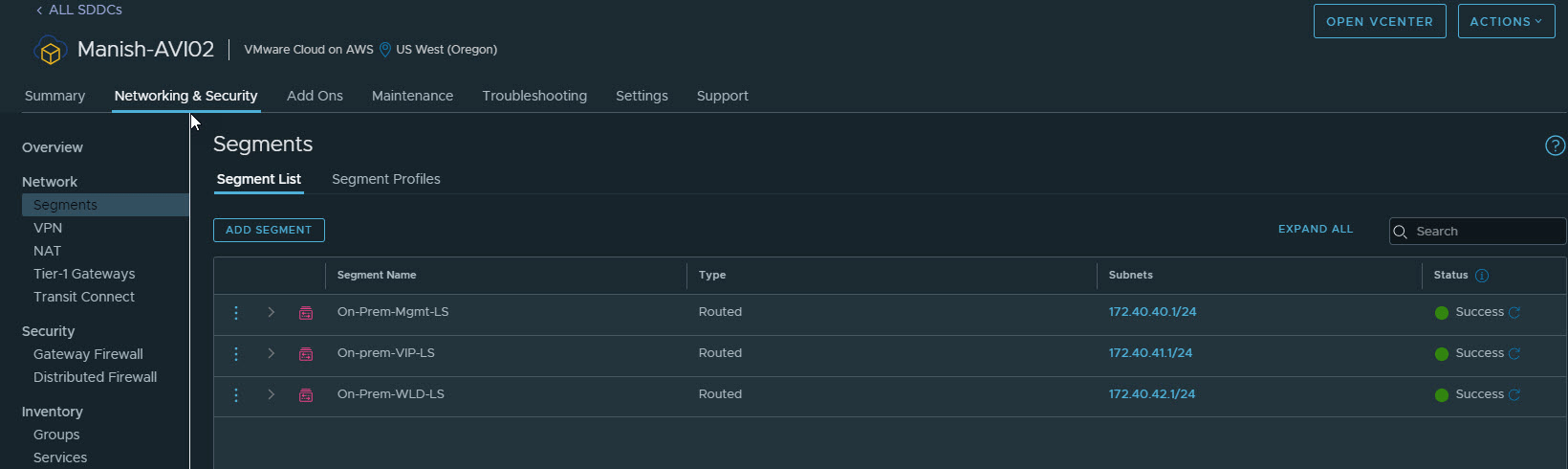
Create Logical Segments
I have the following logical segments provisioned in my SDDC. Avi controllers will connect to the Mgmt-LS segment, and SE VMs will have one leg on Mgmt LS and one on VIP LS.
Web servers that will be load-balanced will be attached to WLD LS.
Deploy Avi Controller
For POC/Lab environments, a single Avi controller will suffice. For production environments, it’s advisable to deploy 3 controllers and cluster them.
Important Note: In VMC on AWS, Avi Load Balancer deployment is supported only in No Orchestrator mode. This is documented in Avi’s official documentation
Avi Controller is available in OVA format, and deployment is straightforward; hence, I am skipping the deployment steps.
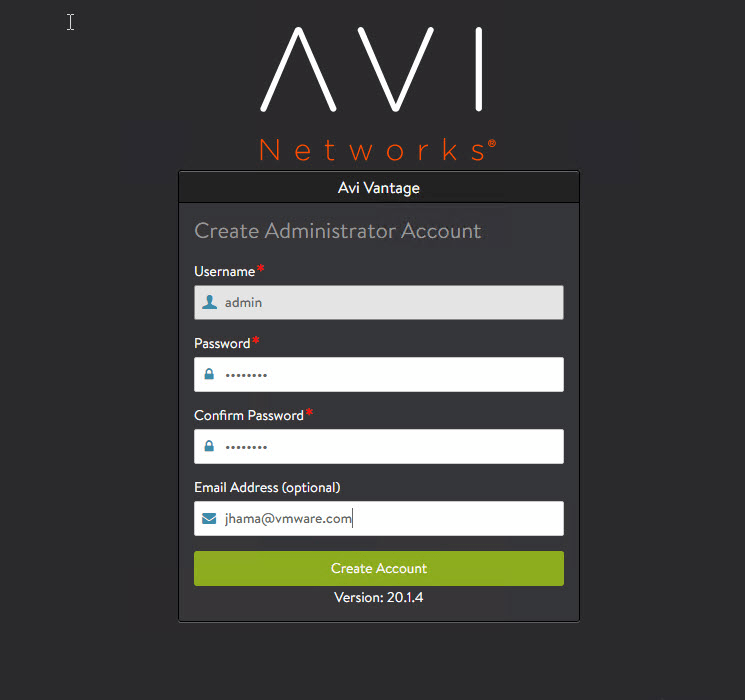
Once the Avi controller VM boots up and services are initialized, connect to the Avi controller GUI by typing https://<avi-controller-fqdn> to finish the initial configuration.
Step 1: Configure credentials and email for the admin user.
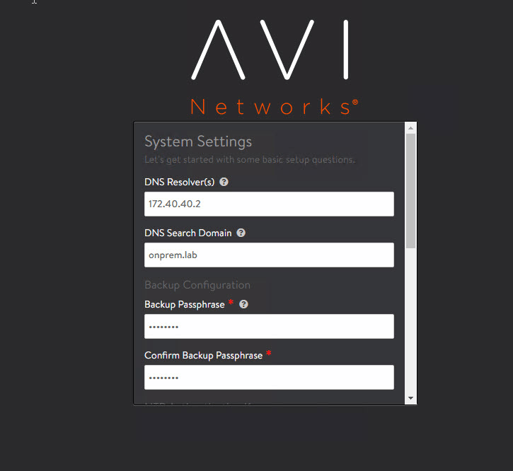
Step 2: Configure the DNS server and backup passphrase.
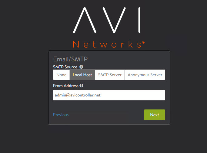
Step 3: (Optional) Configure email settings.
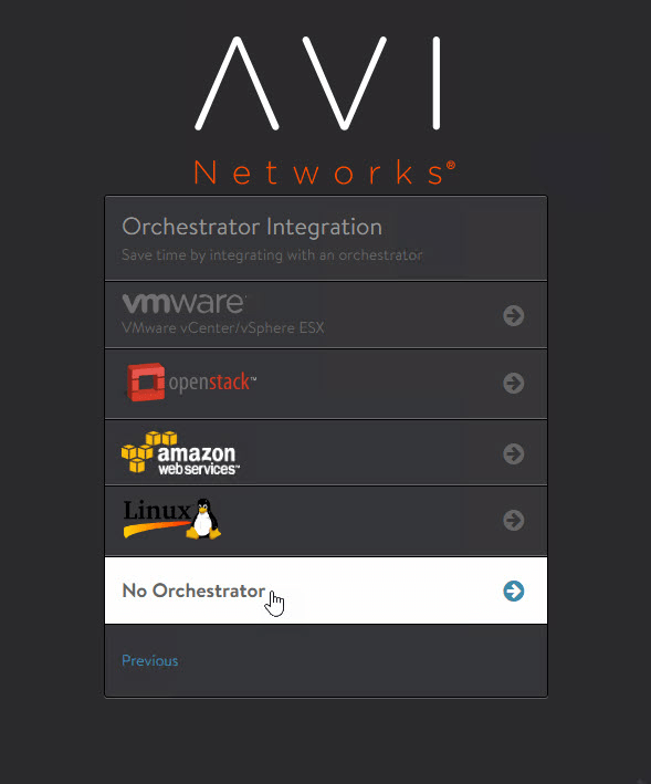
Select No Orchestrator for orchestrator integration.
Select No for multi-tenancy.
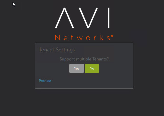
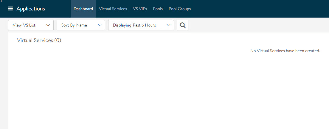
Clicking on No will complete the initial configuration for the Avi Controller, and you will land on the Avi dashboard.
Create and Deploy Avi Service Engine
Since the controller is deployed in the No Orchestrator mode, the Service Engine (SE) VMs will be deployed manually using the OVA file. The OVA file is generated from the Avi Controller portal.
Important: The SE OVA package generated from the Avi Controller is tightly coupled with the generating controller and can’t be used in deployment with any other Avi Controller.
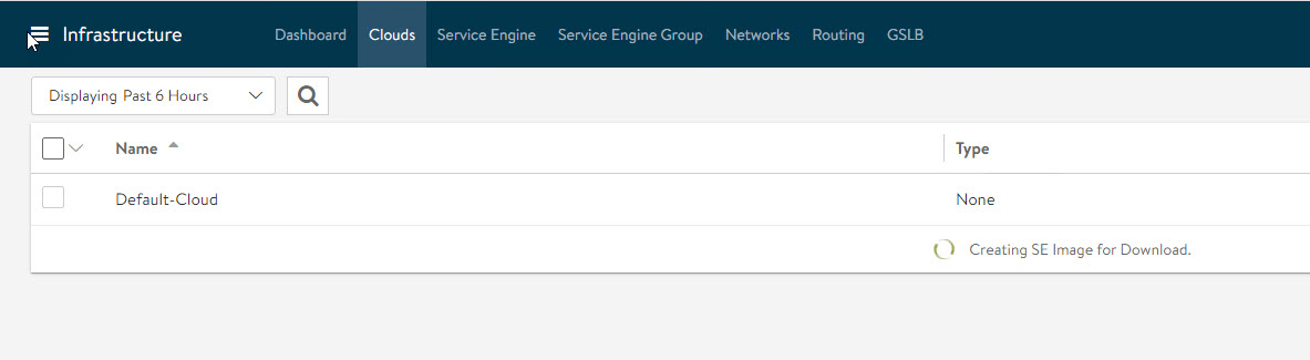
To generate the Avi SE OVA package, navigate to Infrastructure > Clouds > Default-Cloud and click on the arrow button, and select the OVA format.
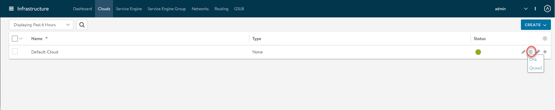
SE image generation takes a couple of minutes and will be downloaded automatically on completion.
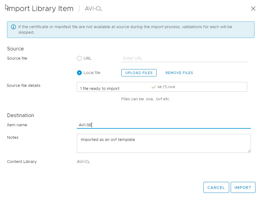
Upload Avi SE ova to Content Library
Service Engine VMs can be created directly from the downloaded OVA file.
For faster deployment of Avi SE VMs, upload the OVA to a content library so that it can be reused without having to upload the OVA to vCenter every time a new SE VM is needed.
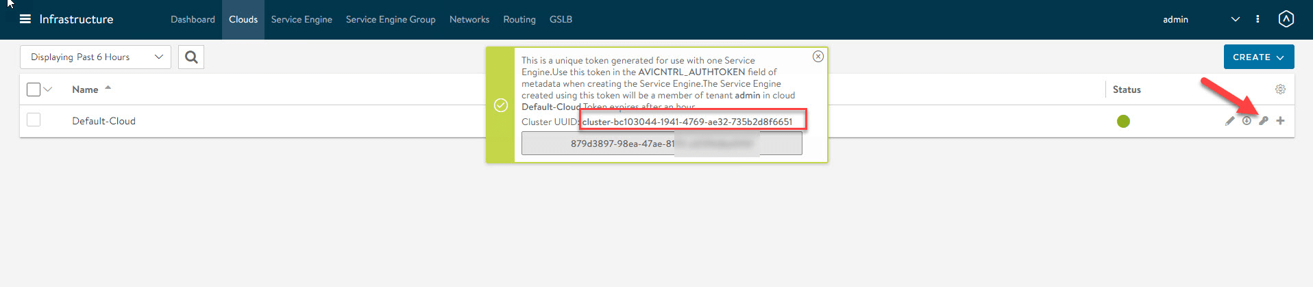
Fetch Cluster UUID and Authentication Token
During Avi SE deployment, we need to pass two parameters: Cluster UUID & Auth Token. These parameters register the Avi SE with the Avi Controller.
To fetch the cluster UUID, go to the Default-Cloud and click the key button, and note the UUID.
Note: If you are deploying multiple SE VMs, then you need an auth token per SE VM.
Deploy Service Engine VM
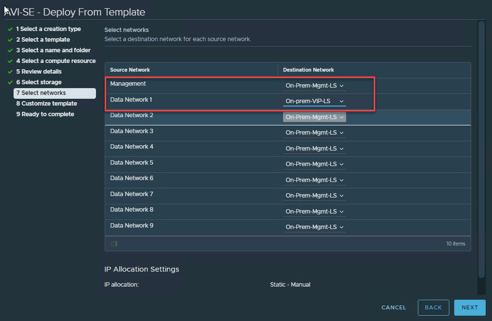
Create a new SE VM by selecting the “deploy from the template” option.
Under the Select Networks page, ensure eth0 is mapped to the Management port group and eth1 to the Avi VIP network.
You can leave Data Network 2-9 to the default setting.
On the customize template page, enter the following info:
- IP Address of the Avi Controller.
- Authentication token for Avi Controller: fetched from the previous step.
- Controller Cluster UUID for Avi Controller: fetched from the previous step.
- Avi SE network information (IP Address/Subnet Mask/GW).
- DNS Server Info.

Repeat the process for deploying additional SE VMs.
Once all SE VMs come up, they will be registered with the Avi Controller, and their status can be viewed under Infrastructure > Service Engine.
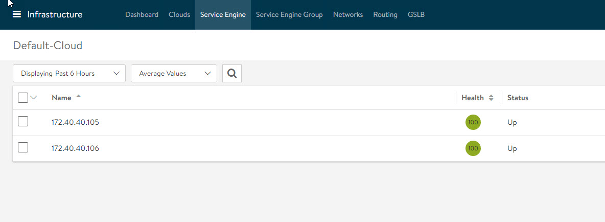
At this point, Avi SE VMs have established the control and management plane communication with the Avi Controller.
The next step is to configure the VIP network to set up the SE data path.
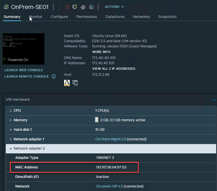
Configure Avi SE Data Network
Note the MAC address of the network adapter associated with the VIP network.
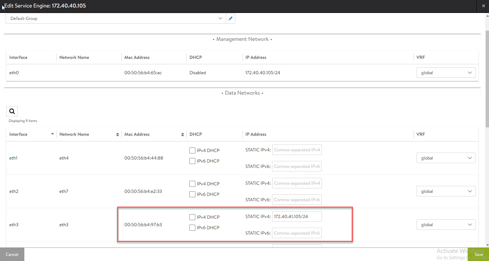
Edit the Service Engine properties.

Find the interface that has the same MAC address you noted earlier, and then enter the IP address that SE VM will use for establishing the data plane.
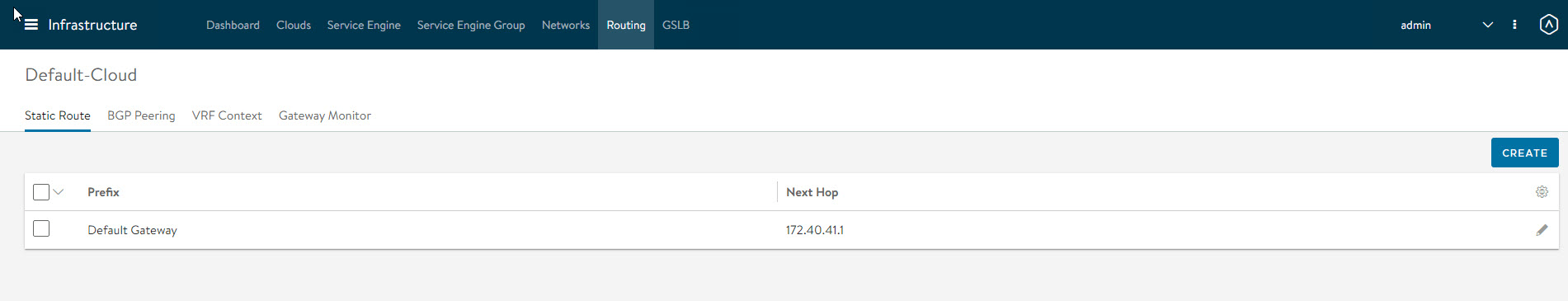
The last step is to add a default gateway for the SE Data network.
To do so, navigate to the Infrastructure > Routing > Static Route page and add a default route pointing to the VIP network default gateway.
Configure DRS Anti-Affinity Rules
For production environments, it’s highly encouraged to have DRS Anti-Affinity rules for the Avi Controller and Avi SE VMs. I am running a single-node SDDC in VMC, so this step doesn’t apply to my setup.
And that’s it for this post. In the next post of this series, I will walk through the steps of configuring the load balancer for a sample web server.
I hope you enjoyed reading this post. Feel free to share this on social media if it’s worth sharing.