
In last post of this series we discussed about distributed logical router and went through some important terms and terminologies. In this post we will jump into lab and will deploy logical distributed router.
If you have missed earlier posts of this series, you can read them from below links:
2: Installing and Configuring NSX Manager
4: Preparing Esxi Hosts and Cluster
5: Configure VXLAN on the ESXi Hosts
7: Distributed Logical Router Tidbits
Before jumping into deploying distributed router, I want to stress on the fact that your logical switches be ready. What i mean here since you wanna test routing between 2 or more different subnets, you should have logical switches ready in place and should have some live VM’s attached to it.
In my lab I have 3 logical switches created for this purpose.

Lets jump into lab now.
1: To Deploy Logical Router login to vSphere Web Client and navigate to Networking & Security -> NSX Edges .Click on ‘+’ to add NSX Logical router.

2: On the New NSX Edge page, select Logical Router option and provide a name,hostname and sweet little description description. If you want your edges highly available, select the checkbox that says “Enable High Availability”. Hit Next to continue.

3: Supply the admin password and set the log level to emergency (if you dont want disk space of your edge appliance getting filled quickly)
I like doing things over ssh, so I have enabled SSH on my edge appliance which will be deployed. Hit next.

Note: If password for your edge appliance is contains less than 12 characters, then you are going to get below warning.

4: On configure deployment page, select the virtual datacenter where LDR will be deployed.
Click on green ‘+’ button which says NSX edge appliances. This will deploy DLR Control VM.

5: Specify the Cluster, Datastore, Host and Folder to deploy the DLR Control VM and hit ok.

6: On the Configure interfaces page, click the select button.
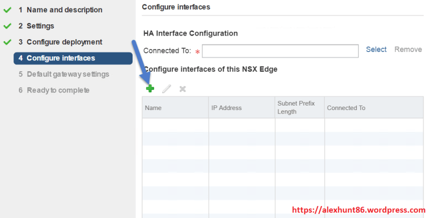
It will open a new window from where you can select the management network for the edge interface.
A note about Management Interface Configuration
Management Interface is not a LIF, it’s local to the Control VM and does not require an IP address assigned and even if you configure one you wouldn’t be able to reach it via a routing protocol because there’s Reverse Path Forwarding (RPF) enabled.

It should look like as shown below. Click on “Configure interface of this NSX Edge” to define your LIF’s.

7: On the Add Interface dialog box, Enter the name of Interface, Select Type, Click Select Link for Connected To: and choose the desired Logical Switch and OK.

Select the logical switch to which your LIF will connect to.

After selecting the logical switch with which this LIF will connect to, we have to define IP address and subnet mask for the LIF.

Using the ‘+’ symbol repeat the wizard until you have created all the LIFs required in your environment.

8: Next and optional, configure a default gateway for the DLR. This typically would be the EGW ip address.

9: On ready to complete page, review your settings and hit finish to start deploying the DLR.

10: Post deployment of DLR, if you navigate to VM and templates view, you will see 2 VM’s deployed (as I chose HA option during deployment). One of these VM will be in active mode and other in standby mode.

Also if you click on NSX edges under Networking and Security, you will se ethe newly created edge listed there.

Double click on the edge and navigate to Manage > Configuration tab, and you can verify from here as well that 2 control VM’s are deployed and one of em is currently active.
You will also find options like changing the edge size from compact to Large or Quad Large, option to define syslog server where edge will route all the logs and option to change HA configuration.

11: On VM and Templates select Logical Router and select Summary tab. Here you will see all the IP’s assigned on your edge VM.

DLR deployment verification steps:
1: Check DLR instance
From NSX Controller run
|
1 |
show control-cluster logical-routers instance all |
This commands shows all the dLR instances and the corresponding hosts (VTEPs) that have joined. This command is very useful when something like routes are not propagated from the Control VM to the hosts.

2: Check Routing Table on ESXi host.
From ESXi, find the DLR name with the command
|
1 |
net-vdr -l -I |

3: Check the routing table installed on the host coming from that dLR
|
1 |
net-vdr -l --route default+edge-1 |

4: On NSX Controller run following commands to see info about MAC Table/ARP table
show control-cluster logical-switches vni 5000 show control-cluster logical-switches mac-table 5001 show control-cluster logical-switches arp-table 5001

Note: In my lab ARP table/Mac Table returns as empty because I dont have any running VM’s connected to my logical switch yet.
I hope you enjoyed reading this post. Feel free to share this on social media if it is worth sharing. Be sociable ![]()
2 thoughts on “Learning NSX-Part-8-Installing Distributed Logical Router”